1. The blanks, materials, and technical requirements of the parts
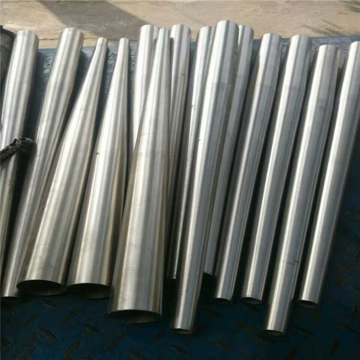
The blank of the thin-walled part is a steel casting, the outline is similar to the part drawing, the machining allowance of each part is about 30mm, and the casting material is ZG310-570. The hardness requirement of the parts is HRC32-36.
2. Difficulties in machining parts
Since the wall thickness of this part is only 9mm, it has all the processing disadvantages of thin-walled parts, such as clamping deformation, cutting deformation, vibration deformation, and thermal deformation. At the same time, the length of the part is large, especially the tapered hole, which requires a long boring bar to clamp the boring tool for turning, which is easy to generate relatively large vibration, thus affecting the accuracy and surface finish of the part.
3. Rough machining of parts
Use a four-jaw single-action chuck to support the inner hole of the blank and align it. Drill the center hole, install a suitable center on the tailstock, and use one clamp and one top to clamp the outer circle of the rough turning. Because the part is long, if the overall feed method is used, the vibration of the part will be aggravated, resulting in the possibility of tool chipping. , so the turning method is adopted with the left and right feed and the middle feed. First, a machine-clamped tool is used to cast the black skin. The parameters are selected: the spindle speed is 30r/min, the cutting amount is 4mm, the feed rate is 0.15mm/r, after removing the black skin, the spindle speed is increased to 100r/min, and the cutting constant feed rate of the quantity parameters is 0.2mm/r, which can be turned to the amount according to the process requirements, and the process chuck is turned out at the same time. Then turn around and use the four-jaw single-action chuck to rough the inner hole. At this time, the ordinary welding tool is used to turn the cast’s black skin. The parameters are selected: the spindle speed is 30r/min, the cutting amount is 2mm, and the feed rate is 0.15 mm/r, after removing the black skin, the spindle speed increases to 70r/min, the cutting amount remains unchanged, the feed rate is 0.2mm/r, and the turning stops when the amount is reached. Due to the large allowance for roughing, the influence factors of clamping, cutting, and thermal deformation may not be considered.
4. Finishing of parts
Finish machining of parts with a lathe. First process the inner hole cone surface, use a four-jaw single-action chuck to hold the outer circle process card position and wrap the outer cone surface with a 10mm thick rubber pad after alignment, which can effectively prevent vibration and deformation. At the same time, the inner cone surface is turned by the method of left and right pick-up to eliminate cutting and vibration deformation as much as possible. Machining with a machine-clamped tool, parameter selection: the spindle speed is 150r/min, the cutting amount is 0.5mm, the feed rate is 0.15mm/r, and the flow rate of the cutting fluid is increased to the maximum, to avoid thermal deformation, at this time, it needs to be processed to the drawing size required. After the inner hole taper surface and each chamfering are completed, turn around to turn the outer taper surface. Use a four-jaw single-action chuck to support the inner hole of Φ314, turn the outer circle of Φ102 to the size, use the tip to support the end, and then start turning the outer cone surface to the requirements of the drawing. Turning the outer cone surface also requires left and right cutters. Clamp tool processing, parameter selection: the spindle speed is 150r/min, the cutting amount is 0.5mm, the feed rate is 0.2mm/r, and the turning is completed according to the drawing requirements. If the left and right tooling method still cannot eliminate vibration when turning the outer cone surface, it is necessary to fill the inner cone hole with rubber or other shock-absorbing items.